Software Availability
The PLANS package does not
operate on current versions of Windows (64-bit). It
may be possible to use the compatibility modes in
Windows to configure a command prompt that can be used
to run PLANS.
The entire PLANS package consists of two files: INSTALL.EXE
and README
EXPORT.EXE,
contains utility programs to convert PLANS data files
into other formats and to convert selected GIS data
formats into formats compatible with PLANS. You should
retrieve and install this file if you are working with
any data files produced by a GIS. See README.EXPORT
for more information.
EXAMPLE.EXE
contains example data for use with PLANS.
The distibution contains very little documentation. For
the most part, PLANS is very user-friendly. |

AN OVERVIEW OF PLANS: PRELIMINARY LOGGING ANALYSIS
SYSTEM
ABSTRACT
This paper presents PLANS (Preliminary Logging Analysis
System), a family of computer programs designed to
facilitate the development of timber harvest plans for
large areas. PLANS supports strategic level planning for
areas ranging in size from 2,000 to 20,000 hectares (4,942
to 49,420 acres). Activity schedules for harvest plans
developed with PLANS typically span from 5 to 25 years.
PLANS relies on digital terrain models (DTM) to provide
elevation data to support the analysis of cable logging
payload, highlead system yarding reach, ground slope and
aspect, and perspective scenes depicting the landscape and
harvest plan features. PLANS interacts with databases
stored in geographic information systems (GIS) by
importing several DTM formats and by exporting harvest
plan related line, point, and polygon features in formats
suitable for inclusion in GIS data layers.
Keywords: Harvest planning, cable logging, digital
terrain model
INTRODUCTION
Successful harvesting in steep terrain requires a thorough
planning effort. The harvest system selected for the
operation, the silvicultural treatment, and the placement
of the harvest system on the terrain influence the
economic and environmental success of timber harvesting
operations. In the case of cable yarding systems, proper
positioning of the cable span permits hauling an ample
volume of logs in each yarding cycle resulting in higher
production and lower costs while minimizing environmental
damage. Improper positioning results in excessive soil
disturbance, reduced production, equipment breakdown,
unsafe operations, or overall inoperable harvest units.
The quality of a timber harvest plan and the actual
harvest operation depends on the planner's thoroughness,
which is influenced by time constraints, management
support, and available planning tools.
The term "harvest planning" can encompass a wide range
of activities and outcomes. Long-range planning, often
spanning several rotations (150 + years), generally
prescribes land allocation strategies and does not
necessarily provide a spatially feasible solution
(Nelson et al 1991). A more site specific approach,
known as area-based planning, involves determination of
specific harvest areas that have a unique geographic
location and subsequent scheduling of the harvest and
road construction activities. PLANS supports area-based
planning. As a precursor to harvest unit and road
scheduling using network solution techniques (Sessions
1987), PLANS enables users to rapidly design and
delineate timber harvest units and road access to timber
over extensive areas. Area-based planning that begins
with well-designed harvest units and transportation
systems can proceed on a solid foundation. The
individual harvest units and road alternatives form the
foundation of the final management plan, and PLANS helps
ensure the operability and soundness of this foundation.
The scenario described for area-based planning varies
according to organizational structure and goals.
However, some basic considerations of timber harvest
planning transcend the details of planning jurisdiction.
One basic consideration is the influence of topography
on the cost and efficiency of timber harvesting.
Topography affects most activities associated with
timber harvesting, from felling and yarding to road and
landing construction. Timber harvest planners therefore
need detailed topographic information. This need has
been traditionally met by topographic maps and aerial
photographs. Reasonably accurate maps with scales
ranging from 1:4,800 to 1:24,000 and contour intervals
of 15 meters (50 feet) or less provide an excellent
foundation for planning. Using such maps, planners can
visualize steepness, ridges, valleys, benches, and
profiles of the terrain in sufficient detail to develop
operable harvest and transportation plans. The
organization and storage of topographic information in a
computer usable form is paramount to the success of any
harvest planning exercise.
BACKGROUND
Burke (1974) suggested using a digital terrain model (DTM)
to supply topographic data for harvest planning. A DTM is
an organized data file containing elevations that
represent the ground surface. A DTM, coupled with the
appropriate software, can provide nearly instantaneous
access to a virtually unlimited number of ground profiles.
Young and Lemkow (1976) developed a prototype timber
harvest planning system that used a DTM. Their planning
system proved that harvest planning using DTM data was
practical. However, their system, limited by computing
horsepower, did not provide an operational solution to
large area planning problems. Reimer (1979) reported that
an operational harvest planning system using DTM data was
successfully implemented by McMillan Bloedel, Ltd., in
Canada. Twito and Mifflin (1982) distributed an early
version of PLANS to USDA Forest Service sites and
industrial sites with compatible computer hardware.
Reutebuch and Evison (1984) reported on an operational
system using DTM data for planning cable logging system
layout available in New Zealand. Twito and others (1987)
distributed an update of PLANS that was operational on a
Hewlett-Packard 32-bit workstation. This system provides
the analytical foundation for the IBM-PC version of PLANS
discussed in this paper.
OVERVIEW OF PLANS
PLANS is a set of computer programs designed to assist
logging engineers and transportation planners as they
develop timber harvest plans for large areas. Typical
candidate areas for application of PLANS range from 2,000
to 20,000 hectares (4,942 to 49,420 acres) with planned
harvest activities spanning from 5 to 25 years. PLANS
allows the planner, aided by an interactive computer
system, to examine a wide range of design and planning
options--a range not possible with earlier planning
methods. PLANS, although it does not fully automate the
design process, enhances the planner's ability to develop
technically sound timber harvest plans. A fundamental
concept underlying PLANS is the use of a digital terrain
model to provide topographic data needed for harvest
planning and transportation system development. By using a
DTM to represent the ground surface, PLANS can quickly
generate ground profiles, ground slope information, aspect
information, and general land form characteristics for use
during the development of a harvest plan. In the United
States, DTM data are typically available in the form of
United States Geological Survey (USGS) digital elevation
models (DEM) that correspond to the standard 7.5-minute
quadrangle map series. The USGS DEM data are arranged in a
30 by 30 meter (98.43 by 98.43 feet) grid with a vertical
accuracy classified as either 7 meter (22.97 feet) RMSE or
15 meter (49.22 feet) RMSE. In general, these data are
sufficient for use with PLANS. An analysis of the adequacy
of USGS DEM data for timber harvest planning (McGaughey
and Twito 1988) showed that USGS DEM data were sufficient
for area-based analysis, where the emphasis is on harvest
and transportation system feasibility. However, the large
grid spacing and possible inaccuracies in the data can
present problems for PLANS users who want to develop a
detailed plan for individual harvest units.
For areas where USGS DEM coverage does not exist, DTM
data must come from an outside source. PLANS does not
provide a tool to develop digital terrain models.
However, the current version of PLANS can read DTM data
from several sources. The underlying requirement for DTM
data to be used with PLANS is that is must be stored
using a gridded structure. For sites using Arc/Info GIS
software (version 6.0), the LATTICEDEM command is
available to convert an Arc/Info lattice file into a
USGS DEM file (ESRI 1991).
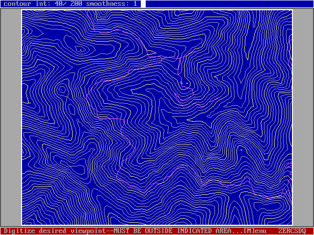
Figure 1. PLANS uses an on-screen contour map to help
users visualize the digital terrain model.
PLANS employs a familiar interface to the topographic
data, an on-screen contour map generated from the
digital terrain model (figure 1), to assist users in
visualizing the terrain data. Landings, unit boundaries,
roads, and other harvest plan components are easily
located and evaluated because users can directly specify
ground locations from the on-screen contour map. PLANS
conducts engineering analyses and encourages users to
investigate several alternative treatments for a given
area before selecting a specific treatment for further
evaluation or implementation. Analysis tools in PLANS
provide design feedback quickly without overwhelming the
user with excessive detail. The analysis tools attempt
to provide summaries of pertinent information to guide
the planner rather than detailed reports of analysis
results. PLANS allows storage and recall of individual
design components and provides tools to integrate
various components into harvest plans. Analysis modules
in PLANS share data, both input and output, to provide a
seamless environment for harvest and transportation plan
development. Links to geographic information systems
(GIS), using a data formatting utility, promote the
integration of timber harvest planning information into
other planning processes, e.g., environmental impact
assessment and long- range planning.
SPECIFIC COMPONENTS OF PLANS
The following are brief descriptions of the analysis
modules currently available in PLANS. The PLANS main menu
shown in figure 2 controls access to these modules.
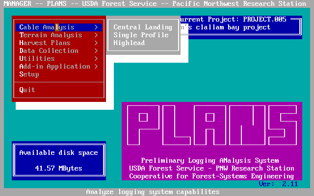
Figure 2. The PLANS main menu provides a user-friendly
interface to all the PLANS programs.
SKYTOWER and SKYMOBIL Programs
The SKYTOWER and SKYMOBIL programs analyze the load
carrying capacity of skyline yarding systems over terrain
profiles extracted from a DTM. The SKYTOWER program
analyzes units yarded in a fan-shaped pattern to a central
tower location. The SKYMOBIL program operates on
individual terrain profiles where the yarder is moved with
each yarding corridor change.
Using SKYTOWER, the planner designates a central
landing by pointing to the yarder location on the
on-screen contour map. The program automatically
generates evenly spaced profiles radiating from the
landing. The maximum span over which a target load can
be yarded is determined for each profile. A planimetric
plot of the resulting unit boundary is then displayed on
the computer screen (figure 3). At this point, the user
can visually assess the overall feasibility of the
landing location. If all spans are short, then either
the target payload was too large or the landing was not
suitable for the yarding system. The user can modify
parameters for individual profiles to adjust the unit
boundary. Possible modifications include increasing the
height of the tailhold, specifying a new tailhold
location, changing the target payload, and specifying
yarding boundaries. A plan or profile view, depending on
the type of modification, shows the results of each
modification.
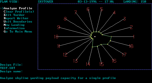
Figure 3. SKYTOWER displays the area that can be yarded
to a central tower location.
SKYMOBIL, like SKYTOWER, conducts profile analysis.
However, SKYMOBIL operates on single terrain profiles
designated by pointing to the profile's beginning and
ending locations. The program extracts the profile from
the DTM and displays the profile on the computer screen.
The planner can then specify the yarder or tailhold
location by pointing to the on-screen profile (figure
4). SKYMOBIL can solve for either the maximum span over
which a specified target payload can be yarded, or the
maximum payload that can be yarded over a specified
span. SKYMOBIL can be very useful in areas requiring
mid-slope roads. A series of parallel profiles running
perpendicular to the contour lines is analyzed to locate
control points for road layout.
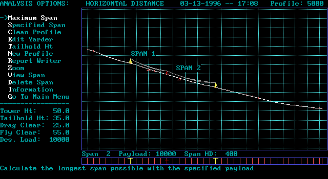
Figure 4. SKYMOBIL allows users to locate the tower and
tailhold on a ground profile.
HIGHLEAD Program
The HIGHLEAD program analyzes settings yarded in a
fan-shaped pattern to a central landing. Like SKYTOWER,
the HIGHLEAD program automatically analyzes evenly spaced
profiles radiating from a user-specified yarder location.
Either the first instance of blind lead along each profile
or the maximum reach of the yarder determines the yarding
limit. HIGHLEAD displays the resulting unit boundary in
plan view and gives the planner the opportunity to modify
the unit boundary. HIGHLEAD allows analysis for
tight-lining (tension the haulback line to increase lift
and permit yarding beyond a point of blind lead). The
planner can also specify yarding limits, change the
tailhold height, or remove profiles entirely to reduce the
area included in the unit boundary.
VISUAL Program
The VISUAL program produces perspective views of terrain,
roads, harvest units, and other harvest plan components
from user-selected viewpoints. These perspective views,
such as the one shown in figure 5, provide a preview of
the visual impact of proposed management activities.
VISUAL also provides an important tool for developing an
understanding of the project area. The perspective
projection of the terrain provides an intuitive picture of
the land form when compared to a topographic map and many
planners find that they are better able to identify subtle
benches and other terrain features when viewing the
perspective projection.
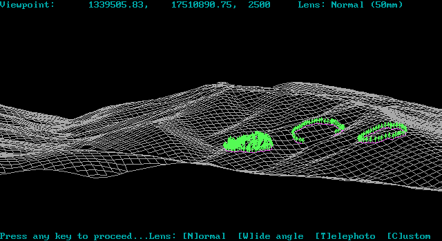
Figure 5. VISUAL produces perspectives of terrain and
harvest plan features.
SLOPE Program
The SLOPE program produces overlays, either on-screen or
hard copy plots, that delineate areas of equal slope,
aspect, or elevation within user-specified categories.
SLOPE can also produce overlays that show any combination
of topographic attributes, e.g., areas with slopes ranging
from 0 to 30 percent (0 to 17 degrees) with northerly
aspect and elevations ranging from 0 to 914 meters (0 to
3000 feet). In addition to overlays, SLOPE also produces
tabular summaries of the slope, aspect, or elevation
information and the land area included in each category.
These attribute overlays provide an excellent aid for
interpreting topographic maps.
PLANCAD Program
The PLANCAD program allows planners to assemble various
harvest plan components into an integrated harvest plan.
PLANCAD can read any design file produced by a PLANS
program and incorporate the appropriate information into a
database that represents the harvest plan. This database
can be exported to other systems, such as geographic
information systems (GIS), for additional analysis.
PLANCAD can also plot harvest plan maps at any scale for
use when communicating planning results. Harvest plans can
be stored and later retrieved for manipulation or output.
Harvest plans are stored as a list of references to the
various design components, so changes to individual design
components are automatically included in the harvest plan.
MAP_REG Program
The MAP_REG program allows planners to register a paper
map mounted on a digitizing tablet to the on-screen
contour map generated from the digital terrain model. The
lower left, lower right, and upper right corners of the
DTM boundary are digitized to register a map. Three
arbitrary points on the map whose ground coordinates are
known can also be used for registration. Any type of map
can be registered using MAP_REG. For example, a map
delineating forest cover types produced by a GIS could be
registered to provide this information to the planner as
they interact with the on-screen contour map.
DIG_DATA Program
The DIG_DATA program helps users enter planimetric data
into PLANS. For example, data sets describing existing
transportation networks and stream systems or a group of
possible landing locations can be built using DIG_DATA.
Various modules in PLANS can access the data files to
provide detailed analysis or simply to provide additional
visual information for the on-screen contour map display.
SQZDTM Program
The SQZDTM program imports digital terrain models into
PLANS. PLANS uses a very compact and somewhat unique data
format to provide rapid access to topographic information.
SQZDTM translates several common DTM formats into the
format expected by PLANS. Formats include USGS DEM, SURFER
(PC-based surface analysis), TerraSoft (PC-based GIS
system), and a generic ASCII format. Any DTM used with
PLANS must first be processed by SQZDTM to ensure
compatibility with the PLANS DTM format.
GRDCONVT Program
The GRDCONVT program translates PLANS output to a variety
of other data formats. GRDCONVT accepts a generic data
format containing the (X,Y,Z) coordinates for the data
points. The coordinates can be converted to a variety of
formats including Arc/Info generate format, AUTOCAD DXF
format, MOSS import format, SURFER boundary file format,
and generic ground profiles containing horizontal
distances and elevations. GRDCONVT allows PLANS users to
share their results digitally with both upstream and
downstream analysis packages.
SUMMARY
The benefits of harvest planning are many. Dollar savings
in the harvesting and hauling cost for an area can result
from several activities carried out during the planning
process. First, by using PLANS to identify the harvesting
and transportation system best suited to the local
conditions, you ensure that operations are feasible.
Second, using PLANS to provide harvest unit and road
locations that provide optimum or near optimum operating
conditions for the selected harvest systems, minimizes
environmental damage. Third, by considering the
interaction of harvest unit locations, road locations, and
silvicultural treatments over many time periods,
scheduling conflicts are minimized and it is possible to
analyze the cumulative effects associated with the harvest
plan.
The use of an intensive preliminary harvest planning
procedure ensures that land managers have based
harvesting decisions on a thorough analysis of all
available data and are seen to be doing so by concerned
public groups. In addition, the analytical tools in
PLANS can provide information to help educate the lay
public about the factors that influence the success or
failure of a harvest operation. This education should
not be under-valued. Managers may find that previous
adversaries are much more willing to participate in the
planning process if they are made aware of and given
access to the analysis techniques being used.
The costs of harvest planning are generally low in
comparison to the harvesting and hauling
costs--generally less than one percent of the total cost
incurred to deliver timber to the market. The planning
cost is justified by the potential for saving 10 percent
or more of the harvesting and transportation costs
through proper selection and application of harvesting
systems (Sauder and Nagy 1977). Economic profits are not
the only justification for better planning. The benefits
of improved harvest plans are often related to better
resource protection and less damage to the environment.
Additional expenditures to support harvest planning can
be justified through net benefit to the environment,
rather than simply considering harvest and
transportation planning as an added cost. Selling the
concept of area-based planning can be a difficult task.
However, PLANS streamlines the area-based planning
process, reducing both the time and money required,
making it possible to implement a level of analysis and
planning previously considered impossible.
COMPUTER SYSTEM REQUIREMENTS FOR PLANS
The minimum recommended computer configuration for PLANS
is:
- IBM-AT compatible computer (80286, 80386SX, 80386DX,
or 80486 processor)
- Hard disk (minimum of 4-6 Mbytes free space)
- 80X87 math co-processor
- 640 Kbytes RAM (512 Kbytes available after boot-up)
- EGA or VGA color graphics
- Microsoft or compatible mouse
- Dot-matrix printer
PLANS will run on a PC-XT with no math co-processor.
PLANS will not function on computer systems equipped
with monochrome graphics adapters (Hercules or
compatible clones).
PLANS supports the use of several digitizer tablets to
allow the registration of paper maps to the digital
terrain model.
REFERENCES
Burke, Doyle. 1974. Skyline logging profiles from a
digital terrain model. In: Proceedings of the 1974 skyline
logging symposium; January 23-24, 1974; Seattle, WA.
Seattle, WA; University of Washington, College of
Engineering. p. 52-55.
ESRI. 1991. Arc/Info command references and user's
guides. Version 6.0. Environmental Systems Research
Institute, Inc. Redlands, California.
McGaughey, Robert J. and Roger H. Twito. 1988.
Large-area timber harvest planning with digital
elevation models. In: Proceedings of the international
mountain logging and pacific northwest skyline
symposium; December 12-16, 1988; Portland, OR. (Place of
publication unknown): (Publisher unknown). p. 87-92.
Sponsored by: Oregon State University, Department of
Forest Engineering and International Union of Forest
Research Organizations, Mountain Logging Section.
Nelson, John, J. Douglas Brodie and John Sessions.
1991. Integrating short-term, area-based logging plans
with long term harvest schedules. Forest Science.
37:101-122.
Sauder, Brent J. and Michael M. Nagy. 1977. Coast
logging: highlead versus long reach alternatives. FERIC
Tech. Rep. TR-19. Vancouver, BC: Forest Engineering
Research Institute of Canada. 51 p.
Reimer, Donald R. 1979. An operational computer
assisted forest engineering system. In: Proceedings of
the International Union of Forest Research Organizations
symposium on mountain logging; September 10-14, 1979;
Seattle, WA: University of Washington, College of Forest
Resources. p. 17-19.
Reutebuch, Stephen E. and David C. Evison. 1984. The
cable hauler planning package: user's guide. FRI Bull.
46. Rotorua, New Zealand: New Zealand Forest Service,
Forest Research Institute. 81 p. Sessions, John. 1987. A
heuristic algorithm for the solution of the fixed and
variable cost problem. In: Proceedings of the Society of
American Foresters symposium on system analysis in
forest resources. Univ. of Georgia, Athens, GA. p.
324-336.
Twito, Roger H. and Ronald W. Mifflin. 1982. Computer
assisted evaluation of skyline thinning opportunities.
In: Proceedings 7306, The small tree resource: a
materials handling challenge; April 19-21, 1982;
Portland, OR. Madison, WI: Forest Products Research
Society. p. 73-79.
Twito, Roger H., Stephen E. Reutebuch, Robert J.
McGaughey and Charles N. Mann. 1987. Preliminary logging
analysis system (PLANS): overview. Gen. Tech. Rep. PNW-
GTR-199. Portland, OR: U.S. Department of Agriculture,
Forest Service, Pacific Northwest Research Station. 24
p.
Young, G. Glen and Daniel Z. Lemkow. 1976. Digital
terrain simulators and their application to forest
development planning. In: Proceedings of the 1976
skyline logging symposium; December 8-10, 1976;
Vancouver, BC. Vancouver, BC: University of British
Columbia Press. p. 81-99.
|